Diagnosing and Fixing Motor Drive Failures in On-Load Tap Changers
When an OLTC motor drive fails to respond, it can leave a transformer locked on a tap that doesn't match grid voltage — or worse, initiate an incomplete tap change. This guide covers the most common motor drive faults, how to diagnose them systematically, and how to restore operation safely.
The Motor Drive's Role in Tap Changer Operation
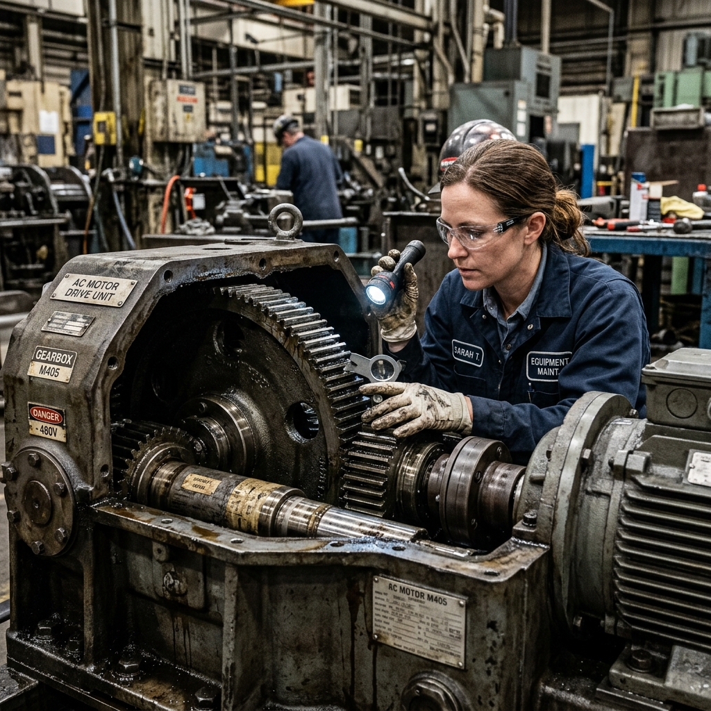
The motor drive unit (MDU) is the electromechanical heart of any motorized OLTC. It receives a raise or lower command from the RTCC panel or local control switch, energizes a motor to wind the energy accumulator spring, and releases it at precisely the right position to execute the diverter switch action. The drive also monitors position through limit switches and end-of-travel protections to prevent over-travel or repeated operation on the same tap.
Because the MDU contains both electrical components (motor, contactors, limit switches, relays) and mechanical components (gears, shafts, couplings, position indicators), faults can originate from either domain — and diagnosing them correctly determines whether you need a board replacement or just a limit switch adjustment.
The Five Most Common Motor Drive Faults
1. Motor Fails to Start on Command
When the RTCC panel sends a raise or lower command and the MDU motor does not energize, start diagnosis at the control circuit, not the motor itself. In the large majority of cases, the fault is in the control path:
- Check the control fuse in the MDU panel — a blown fuse on the control circuit is the most common single cause of non-response.
- Verify incoming control voltage at the RTCC panel output terminals using a multimeter. Many site engineers waste time inside the MDU when the RTCC panel itself has lost its auxiliary supply.
- Inspect the motor contactor coils. Contactors for raise and lower directions are separate. Use the RTCC panel's manual local control to confirm which direction the fault appears on — if both directions fail, suspect the control supply or common path. If only one direction fails, isolate that directional contactor.
2. Motor Runs But Tap Position Does Not Change
This fault typically means the mechanical coupling between the motor shaft and the OLTC drive shaft has failed. Check:
- Coupling shear pin or jaw coupling: A shear pin is a deliberate weak point designed to fail before damage reaches the OLTC mechanism. Inspect the coupling at the MDU output shaft — if the shear pin is broken, replace it with the correct grade (never substitute a higher-strength pin).
- Drive shaft alignment: After any field repair or MDU replacement, shaft misalignment causes high torque and eventual coupling failure. Check alignment with a dial gauge.
- Gear train binding: Open the MDU gear inspection cover and look for grease degradation, foreign material, or chipped gear teeth that prevent free rotation.
3. Tap Change Completes But Position Indicator Reads Incorrectly
The position indicator in the MDU drives both the local mechanical display and the remote position signal to the RTCC panel and SCADA. If the physical tap changed but the indicator reads wrong:
- Check the position transmitter coupling — a loose gear between the drive shaft and transmitter shaft causes count errors that compound with each operation.
- On older MDUs with potentiometer-type position transmitters, measure the transmitter output at each tap position. Erratic or non-linear output means the potentiometer track is worn and requires replacement.
- On modern MDUs with digital encoders, check the encoder power supply and signal cable continuity to the RTCC panel.
4. Motor Runs Continuously and Does Not Stop (Run-Away Condition)
A continuously running motor is a serious fault that must be stopped immediately by cutting the motor supply at the MDU local isolator. This fault means the motor's stopping circuit has failed. Common causes:
- Stuck or misadjusted limit switch: The end-of-travel limit switch that opens the motor circuit at the correct position has not operated. Inspect the limit switch cam for wear, and check that the adjustment is within the manufacturer's specification.
- Welded motor contactor contacts: If the motor contactor contacts have welded together due to repeated inrush current, the control circuit cannot de-energize the motor. Replace the contactor immediately — this is a common failure in hot environments and on MDUs that perform high daily operation counts.
- Position counter failure: In electronic MDUs, the controller may have lost its position reference and is searching for a valid position. This requires a full MDU re-initialization procedure as specified by the manufacturer.
5. Incomplete Tap Change — Motor Stalls Mid-Operation
An incomplete tap change is among the worst outcomes — the OLTC mechanism is left in an intermediate position, which can result in a half-engaged selector switch contact carrying load current at a reduced contact area. This causes severe arcing and contact erosion. Causes include:
- Insufficient motor torque: Motor winding insulation breakdown reduces motor torque. Measure motor winding resistance (all three phases for 3-phase motors) and compare to nameplate values. A difference of more than 5% between phases indicates a developing fault.
- Mechanical obstruction inside OLTC: Sludge buildup in heavily carbonized oil can physically resist the selector switch movement. This requires a full OLTC internal inspection and cleaning.
- Low supply voltage to motor: Measure the actual voltage at the motor terminals during an operation attempt. A voltage drop of more than 10% below rated voltage significantly reduces motor torque on induction motors.
Safe Diagnostic Procedure on a Live Transformer
Many of these checks are performed while the transformer is energized and supplying load. Follow these non-negotiable safety rules before opening the MDU panel:
- Inform the substation or plant control room that you are working on the OLTC control circuit — they must not issue remote voltage regulation commands during the diagnostic period.
- Disable AUTO mode on the RTCC panel — place the RTCC in MANUAL or LOCAL mode to prevent unsolicited AVR commands from initiating tap changes while your hands are inside the control wiring.
- Use insulated tools rated for the control circuit voltage (typically 110V AC or 220V AC depending on the substation control supply standard).
- Never open the diverter switch compartment of the OLTC while the transformer is energized. The MDU and control panel can be accessed safely — the high-voltage OLTC internal mechanism cannot.
When to Replace vs. Repair a Motor Drive Unit
Motor drives from manufacturers like ABB (Reinhausen), MR Type BUE/BUAD, and CTR can often be repaired at component level — contactors, relays, limit switches, and position transmitters are all individually replaceable with standard parts. However, replacement of the entire MDU is the better choice when:
- The motor has burnt winding insulation (indicated by burning smell, discoloration, or winding resistance imbalance)
- The gear train has chipped or cracked teeth that cannot be individually replaced
- The MDU frame or housing has physical damage from moisture ingress (visible corrosion on the PCB boards of electronic MDUs)
- The original manufacturer has discontinued support and spare parts for that MDU model
Conclusion
Motor drive faults in OLTCs are almost always diagnosable with a systematic, signal-tracing approach — from control supply, through the contactors, to the mechanical coupling and limit switches. The key is isolating whether the fault is in the electrical control chain, the motor itself, or the mechanical drive train, and addressing each domain with the correct tools and safety precautions.
Sairaj Groups stocks replacement components for most common OLTC motor drive units including limit switches, contactors, position transmitters, and drive couplings. Our field teams also carry out on-site MDU repairs and adjustments across Maharashtra, reducing transformer downtime from multi-day logistics delays to same-day resolution.

Technical Team
Subject Matter Expert
Technical Team brings years of technical expertise in transformer maintenance and OLTC diagnostics.
Tags
Related Articles

Complete Guide to OLTC Maintenance: Best Practices 2026
Learn essential OLTC maintenance procedures, inspection schedules, and preventive measures to extend transformer life and ensure grid stability.
Transformer Oil Filtration in OLTC Systems: A Complete Field Guide
Learn about transformer oil filtration for OLTC systems. Discover critical oil quality tests, intervals, and the high-vacuum process to prevent failure.
How OLTC Switching Sequences Work: Diverter Switch & Selector Switch Explained
Understand the complex OLTC switching sequence. Learn how diverter and selector switches safely change transformer taps under full load without power loss.