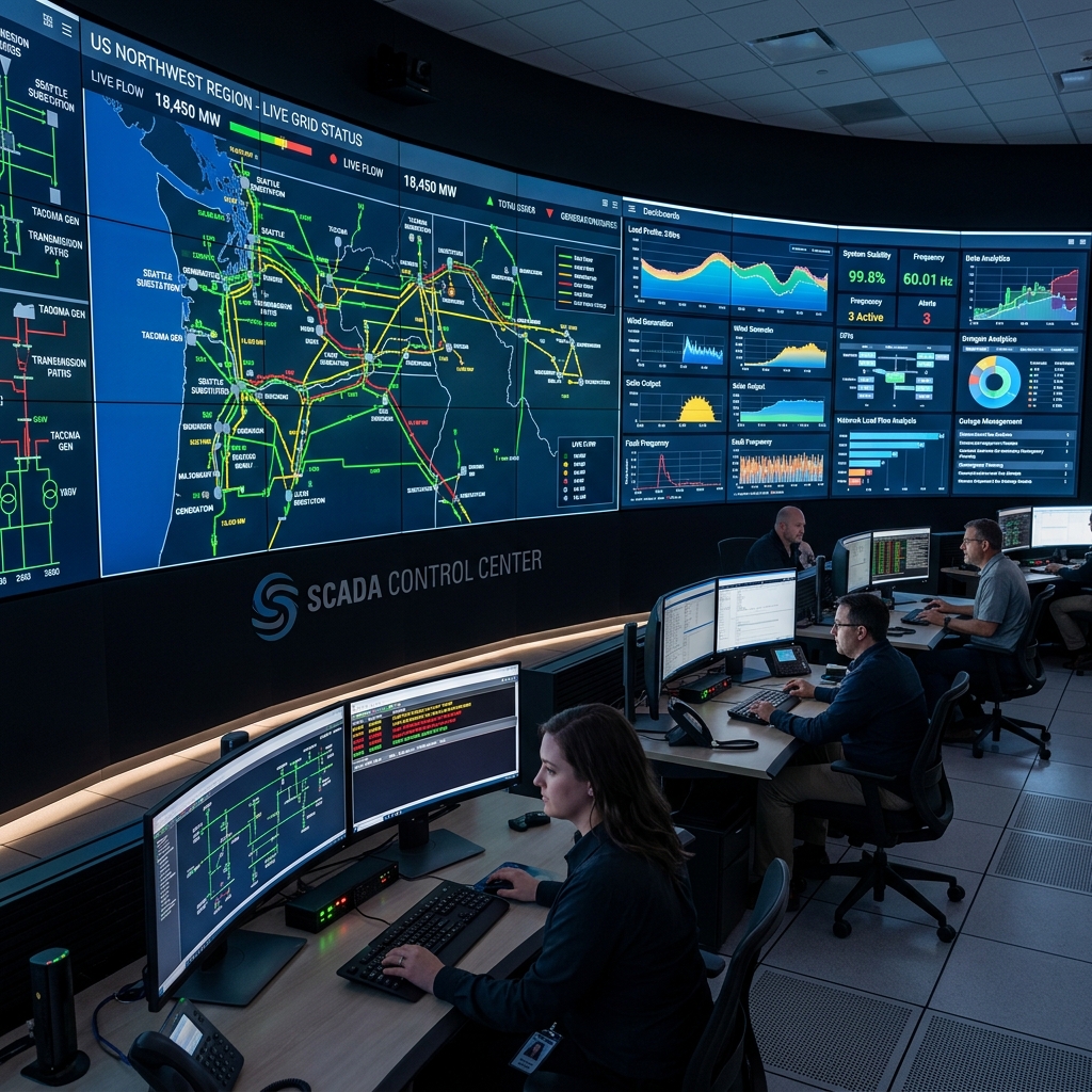
Integrating RTCC Panels with SCADA Systems for Modern Power Grid Control
Modern power utilities are moving away from manual tap changer control toward fully integrated SCADA-driven voltage regulation. This guide explains how RTCC panels communicate with SCADA systems using IEC 61850, Modbus RTU/TCP, and DNP3 protocols — and how to configure AVR set-points for stable grid operation.
Why SCADA Integration Matters for Tap Changer Control
In a traditional substation, the RTCC (Remote Tap Changer Controller) panel sits in the relay panel room and manages voltage regulation automatically through its internal AVR (Automatic Voltage Regulator) logic. Operators interact with it locally or over dedicated two-wire control circuits from the control room desk. This setup works — but it is effectively an island of automation, blind to the wider grid state and inaccessible for remote monitoring without physical presence.
Modern Energy Management Systems (EMS) and SCADA platforms demand that every intelligent electronic device — including RTCC panels — share real-time data and accept control commands over standardized communication protocols. An RTCC panel that cannot report its current tap position, voltage measurement, and operation count to SCADA is an operational liability in today's grid environment.
Communication Protocols Used in RTCC-SCADA Integration
IEC 61850: The Modern Substation Standard
IEC 61850 is now the preferred communication standard for new substation automation projects in India, adopted by Power Grid Corporation of India (PGCIL), most state TRANSCO companies, and large industrial clients. For OLTC control, IEC 61850 defines specific logical nodes:
- ATCC (Automatic Tap Changer Controller): Represents the AVR function — its set-point voltage, bandwidth, and control mode (auto/manual) are accessible via GOOSE messages and MMS services.
- YLTC (Load Tap Changer): Represents the physical OLTC — current tap position, operational status, and command objects (raise/lower) are mapped here.
When specifying a new RTCC panel for IEC 61850 projects, confirm that the panel's communication card supports both GOOSE (for fast peer-to-peer event messages) and MMS (for client-server data reporting to the EMS/SCADA server).
Modbus RTU / Modbus TCP: Legacy and Mid-Range Integration
Modbus remains the most widely used protocol in Indian industrial substations and smaller utility feeders because of its simplicity and broad device support. Most RTCC panels manufactured in India — including models from Sairaj Groups — support Modbus RTU (over RS-485) as standard and Modbus TCP (over Ethernet) as an option.
Key Modbus register mappings for RTCC panels typically include:
- Holding Register: Current tap position (integer, 1 to N)
- Holding Register: Measured secondary voltage (in volts × 10 or × 100 for decimal resolution)
- Holding Register: AVR set-point voltage
- Coil: Raise command (momentary pulse from SCADA)
- Coil: Lower command (momentary pulse from SCADA)
- Coil: Auto/Manual mode selection
- Input Register: Operation count since last reset
Always obtain the specific Modbus register map from the RTCC panel manufacturer before programming the SCADA RTU or DCS. Register addresses vary between manufacturers and even between different firmware versions of the same panel model.
DNP3: Utility SCADA Applications
DNP3 (Distributed Network Protocol 3) is common in utility SCADA systems from vendors like GE, ABB, and Siemens. It is specifically designed for reliable communication over noisy serial and IP links typical of transmission substation environments. DNP3 uses object groups to map OLTC data: Analog Input objects for measured values, Binary Input objects for status flags, and Control Relay Output Block (CROB) objects for raise/lower commands.
For greenfield utility projects, IEC 61850 is now strongly preferred over DNP3 for new installations, though DNP3 retrofit remains common when integrating new RTCC panels into existing DNP3-based SCADA systems.
Configuring the AVR Set-Point for Grid Stability
Incorrect AVR configuration is the leading cause of transformer OLTC hunting — a condition where the tap changer continuously oscillates between two adjacent taps because the bandwidth is set too narrow or the time delay is too short. This rapid cycling causes severe contact wear and can exhaust a transformer's mechanical tap change life within months instead of years.
Set-Point Voltage
The AVR set-point voltage represents the desired secondary bus voltage that the AVR tries to maintain by issuing raise/lower commands. Set this value at the nominal secondary voltage specified in the transformer name plate — typically 11 kV, 33 kV, or 0.433 kV depending on the transformer winding. If the substation bus voltage fluctuates seasonally (common in agricultural feeders in Maharashtra), the set-point may need seasonal adjustment — a function supported by SCADA-programmable RTCC panels.
Bandwidth (Dead Band)
The bandwidth defines a voltage range around the set-point within which the AVR takes no action. A bandwidth that is too narrow (for example, ±0.5% on a 33 kV bus = ±165 V) means normal grid voltage fluctuations constantly trigger tap changes. A bandwidth that is too wide (for example, ±5%) means the transformer output deviates significantly from the set-point before correction occurs.
Industry practice for Indian distribution and sub-transmission transformers:
- Distribution transformers (11 kV secondary): Bandwidth of ±2% to ±3% (±220 V to ±330 V on 11 kV)
- Grid transformers (33 kV / 132 kV secondary): Bandwidth of ±1.5% to ±2%
- Industrial transformers with tight process voltage requirements: Bandwidth of ±1% to ±1.5%
Time Delay (Intentional Delay)
The intentional time delay — typically 30 to 120 seconds — prevents the AVR from responding to momentary voltage dips and swells that resolve themselves (motor starting, switching events). Only if the voltage remains outside the bandwidth for the full delay period does the AVR command a tap change.
Setting the delay correctly requires analyzing the voltage profile of the specific bus over a 24-hour period. Substations with frequent short-duration voltage events (industrial parks with large motor loads) need delays of 60–90 seconds. Quiet residential feeders with slow, predictable voltage variations can use shorter delays of 30–45 seconds.
Parallel Transformer Operation and RTCC Coordination
When two or more transformers operate in parallel on the same bus, their tap positions must remain coordinated. A difference of more than one tap position between parallel transformers drives a circulating reactive current that increases losses and stresses winding insulation. RTCC panels handle this through two coordination methods:
- Master-Follower (Leader-Follower): One transformer's RTCC is designated master. It controls its own tap changes based on AVR logic, and simultaneously sends a command to follower RTCCs to match its tap position. Simple and reliable, but the follower's AVR logic is bypassed.
- Circulating Current Method: Both RTCCs measure the circulating current between transformers. If a tap difference causes circulating current above a threshold, the lagging transformer is commanded to raise its tap position to match. More sophisticated, handles transient tap differences without requiring a dedicated inter-RTCC communication link.
When ordering RTCC panels for parallel transformer applications, always specify the coordination method during enquiry so the panel manufacturer can include the correct communication card, current transformer inputs, and logic settings.
Testing Your RTCC-SCADA Integration Before Commissioning
Before energizing a new transformer with SCADA-integrated RTCC control, perform these integration tests from the SCADA workstation:
- Read the current tap position register — verify it matches the physical position indicator on the MDU.
- Issue a Raise command from SCADA — confirm the MDU operates and the tap position register increments correctly.
- Issue a Lower command from SCADA — confirm operation and register decrement.
- Read the measured secondary voltage — compare against a calibrated voltmeter connected to the secondary PT secondary terminals.
- Switch the RTCC from Manual to Auto mode via SCADA coil — confirm the AVR LED on the RTCC panel illuminates and the panel accepts the mode change.
- Simulate a voltage deviation: temporarily adjust the AVR set-point in SCADA so the measured voltage falls outside the bandwidth. Confirm that after the configured time delay, the RTCC automatically issues a tap change command without any manual intervention.
Conclusion
RTCC panel and SCADA integration is no longer optional for modern power infrastructure. Whether your application involves a new grid-scale substation using IEC 61850 or a brownfield industrial plant upgrading its Modbus-based automation, the RTCC panel is the key interface between digital control and physical voltage regulation.
Sairaj Groups manufactures RTCC panels with built-in Modbus RTU, Modbus TCP, and optional IEC 61850 communication interfaces. Each panel is factory-tested with the specific register map and protocol configuration required by the client's SCADA or DCS system before dispatch. Contact our engineering team for a detailed specification review and quotation tailored to your project requirements.

Engineering Team
Subject Matter Expert
Engineering Team brings years of technical expertise in transformer maintenance and OLTC diagnostics.
Tags
Related Articles

Complete Guide to OLTC Maintenance: Best Practices 2026
Learn essential OLTC maintenance procedures, inspection schedules, and preventive measures to extend transformer life and ensure grid stability.
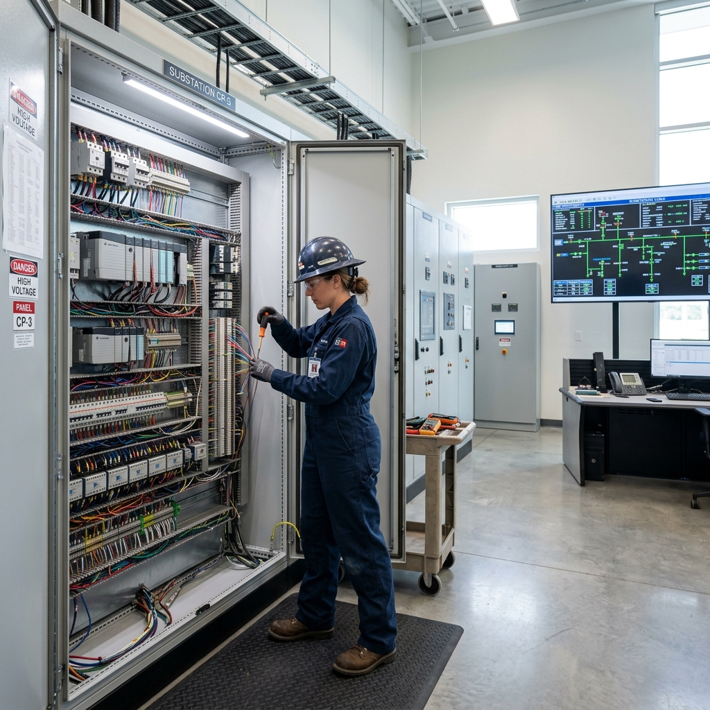
RTCC Panel Installation: Step-by-Step Technical Manual
A complete step-by-step RTCC panel installation guide, covering wiring diagrams, safety protocols, and commissioning for stable voltage regulation.
Transformer Oil Filtration in OLTC Systems: A Complete Field Guide
Learn about transformer oil filtration for OLTC systems. Discover critical oil quality tests, intervals, and the high-vacuum process to prevent failure.